Home -- Basic Multifrequency Tympanometry
Basic Multifrequency Tympanometry:
The Physical Background
by
Joachim Gruber
(a pdf version of this document can be found at this
address)
In tympanometry the mobility of the tympanic membrane is measured while
the membrane is exposed to a (sinusoidal) tone of frequency f.
In the ear, the tympanic membrane is mechanically coupled with the middle
ear ossicles to the oval window -the interface between middle and inner
ear. It is this entire system (membrane, middle ear, oval window) that
is forced into oscillation. The oscillation is detected by a microphone.
(A more detailed description is given in "Tympanometry
in just seconds".)
A linear theory used to evaluate the signal from the microphone is presented
here. The response of a linear system when driven by a periodic oscillation
can be expressed in terms of the resistance with which the system responds
to the excitation (called "impedance") or in terms of the ease with which
it is set into motion (called "admittance"). Both expressions of the response
are presented here next to each other in a table.
An excellent summary of the linear theory, and a review of its practical
applications and the reliability of multifrequency tympanometry in diagnosing
middle ear diseases is:
Robert H. Margolis, Lisa L. Hunter,
Acoustic Immittance Measurements, Chapter 17 of Audiology:
Diagnosis, by Ross J. Roeser, Michael Valente, Holly Hosford-Dunn (eds),
Thieme 2000.
I. Forced Linear Oscillations
Mechanical Impedance
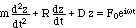
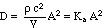
Assumption 1 (Hooke's law)
Let m be a mass on a spring and F the force resulting from an elongation
z of the spring. Then Hooke's law approximates the force F as being proportional
to z
(1) 
D is the Hook spring constant (compliance).
|
Mechanical Admittance
|
| Let t be the time variable. |
. |
Assumption 2 (velocity proportional friction)
When the mass moves, it is slowed down by friction R. Let the friction
force be proportional to the speed v of the movement

(2) 
where R is the friction coefficient.
|
. |
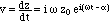
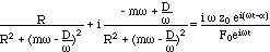
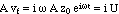
Definition 1 (periodic force)
Let
(3) 
be a force wiggling at mass m with
 . .
 is the imaginary unit.
F0 is the amplitude of the force keeping the mass m in oscillatory
motion. is the imaginary unit.
F0 is the amplitude of the force keeping the mass m in oscillatory
motion.
|
. |
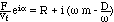
To wiggle at mass m, force F has to be the sum of the following forces
-
 (force to
overcome the inertia of the system), (force to
overcome the inertia of the system),
-
 (force
to counteract the friction), (force
to counteract the friction),
-
 (force
necessary to overcome the tension of the spring). (force
necessary to overcome the tension of the spring).
|
. |
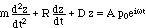
Theorem 1 (equation of motion)
The resulting movement of the mass can be calculated from the force
balance
F = Fm + FR + FH, i.e.
(4) 
|
. |
Assumption 3 (periodic movement).
Let mass m oscillate with frequency  and let this oscillation be out of phase (in comparison with the oscillation
of force F) by
and let this oscillation be out of phase (in comparison with the oscillation
of force F) by 
(5) 
|
. |
| The velocity v of mass m is then
(6) 
Abbreviate
(7) 
|
. |
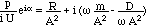
Theorem 2 (system response)
The response of system (4) can be characterized by the ratio between
force F and velocity vf
(8) 
Proof:
Plugging (5) into (4), and then dividing both sides of
(4) with
 yields yields
(9) 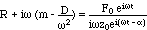
Substituting (3) and (7) in (9) gives us (8).
|
Theorem 2' (alternative system response)
Alternatively, the system response can be characterized by the ratio
between velocity vf and force F
(8') 
Proof:
The reciprocal of (9) is
Substituting (3) and (7), this can be written as

|
| Definition 2 (impedance)
(10) 
This ratio (10) will be called mechanical impedance Zm. The
real and imaginary parts of the sum have the following names:
resistance R
reactance 
mass reactance 
compliant reactance  |
Definition 2' (admittance)
(10') 
In (10') the following abbreviations are used:
admittance 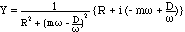
conductance 
susceptance 
mass susceptance 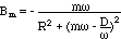
compliant susceptance 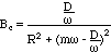 |
II. Acoustics
Acoustic impedance
|
Acoustic admittance
|
Let  V be a fast
(adiabatic, i.e. heat non-dissipating) change of a volume V of air and P
the corresponding pressure change. V be a fast
(adiabatic, i.e. heat non-dissipating) change of a volume V of air and P
the corresponding pressure change. |
. |
Definition 3 (compressibility  ) )
The adiabatic compressibility of air is defined as
(11) 
|
. |
Theorem 3
The compressibility can be expressed in terms of the density  of the air and the speed of sound c in air:
(12) 
Proof can be found in textbooks of physics.
|
. |
| Let volume V be approximated by a cylinder with base A (and a height
h). |
. |
Definition 4 (cross section A of air volume)
Then volume change V
can be expressed as change z of the cylinder height
(13) 
|
. |
| The corresponding pressure change P
can be written in terms of the force F on A
(14) 
|
. |
Definition 5 (Hooke's constant D for air, acoustic stiffness
Ka)
Combining (11) - (14) the force
F resulting from the volume change V
can be written similarly as Hooke's law
(15) 
with the abbreviation
(16) 

where (see (11), (12)) 
|
. |
Assumption 4 (friction R)
Let the volume V of air dissipate energy similarly as the mass m on
a spring in (2):

|
. |
Assumption (rigid body of oscillating masses)
The periodic oscillation of the air in the ear canal wiggles at the
tympanic membrane, the middle ear ossicles etc. This has been ignored in
the system dealt with until now.
Let us assume that all those masses comprise a rigid entity meff
that oscillates as a whole and in phase with the air in the ear canal.
In other words, the masses of which meff is composed do not
oscillate separately and out of phase with the air.
Definition 7 (oscillating mass m)
The total oscillating mass m is therefore the mass V
of the air plus the effective mass:
m = V + meff
Thus, the force to overcome the inertia of m is
(17) 
|
. |
Theorem 4 (equation of motion)
As in the case of the mechanical oscillator, the resulting movement
of the air particles in volume V can be calculated from the force balance
F = Fm + FR + FH, where

(18) 
(18a) 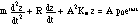
|
. |
| For a periodic pressure being applied by a loudspeaker to the ear canal
air and mass meff (assumption 3), the system's response is analogous
to (8) (note that again F = A p):
(19) 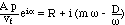
|
. |
Definition 6 (volume velocity U)
Volume velocity U is defined as the volume that flows through the air
canal cross section per unit time:
|
. |
| It is customary to replace vf in (19)
with iU/A. Deviding both sides of (19) by A2
we get the following expression chaaracterizing the system response
(20) 
Definitions 7 (acoustic resistance Ra,
acoustic inertance M)
(1) To simplify the form of the equations, we will introduce the
acoustic resistance
 . .
(2) Likewise, Kinsler and Frey (1962,
p. 190 (Eq. 8.14)) introduced the definition of acoustic inertance
 . .
Using (16), the last term on the right hand side
can be simplified:
(21) 
|
. |
Theorem 5 (system response)
The final expression for the system response is (20).
In analogy with (10) the ratio (22)
is called acoustic impedance Za
(22) 
|
Theorem 5a (alternative system response)
Alternatively, the system response can be characterized by the inverse
of ratio (22)
(22') 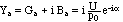 |
Definition 8 (acoustic impedance Za)
The impedance Za given in (22) has a
real and an imaginary part (see (20)).
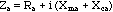
With definitions 7.1 (acoustic
resistance Ra) and 7.2 (acoustic
inertance M) and definition 5 (acoustic stiffness
Ka) the acoustic impedance can be written in analogy with
definition
2, and the following names are given:
(23)
resistance Ra
reactance 
mass reactance 
compliant reactance 
|
Definition 8' (acoustic admittance
Ya, eqs. (23'))


(23')
conductance 
susceptance 
mass susceptance 
compliant or stiffness susceptance 
|
| . |
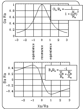
Fig. 1: GaRa and BaRa
as a funtion of Xa/Ra. At |Xa|/Ra
= 1 Ga Ra and Ba Ra have the
same size. At resonance GaRa = 1 and BaRa
= 0.
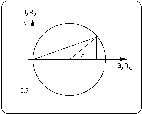
Fig. 2: Oscillation plotted in {GaRa,
BaRa} plane lies on a circle with radius 1/2, because
GaRa2+ BaRa2
= (1/2)2 for all Xa/Ra. The angle
will be used to calculate Ra from tympanographically meaasured
Ga and Ba.
|
| . |
Fit of Ra to multifrequency tympanogram Ga(f)
and Ba(f)
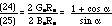
Definition of
(see Fig. 2)
(24)
(25) 
From (23), (24) follows
(26) 
Proof:
Multifrequency tympanogramm gives Ga(f) and Ba(f)
. Thus (26) is a function of the immission frequency
f. (26) can be solved for
as a function of f.
With (25) Ra can be fitted to the tympanogram
(27) 
|
Definition 9 (resonance frequency r)
Let the frequency at which the reactance Xa and susceptance
Ba vanish be called resonance frequency r
of the system
 .
.
Solving for r
(28) 
At resonance r
conductance and resistance are simple reciprocals of each other:

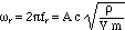
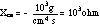
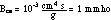
| Data:
(d1) 
At f = 226 Hz
(d2) 
Plugging (d1) and (d2) into the definition of Xca
above
(d3) 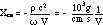
A volume V = 1 cm3 of air has a compliant reactance
|
At high positive or negative ear canal
pressures the tympanic membrane is almost fixed and the middle ear is nearly
motionless (meff approx. 0, Ra approx. 0) the admittance Ya
= Ba = Bca (the latter because Xma <<
Xca) with

Since Bca can be determined experimentally, the ear canal
volume V can be calculated from this equation. At f = 226 Hz

A volume V = 1 cm3 of air has a compliant susceptance
|
III. Parameter determination from multifrequency
tympanometry
III.1 Single resonance frequency system
Fit of V and m/A2 to Xa/Ra
Use definitions 8 (23)
of Xma and Xca:
(23.1) 
(23.2) 
In detail (see Fig. 3):
-
Plot log|Xa| as a funtion of logf as
shown below.
-
Intersections of asymptotic lines with y-axis at logf = 0 give
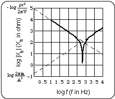
Fig. 3: Extrapolation of Xca(f) and
Xm(f) yields V and m/A2.
Another possibility, using (28), see
Fig. 4:
Ear canal cross section A together with oscillating mass
m can be fitted to the resonance frequency fr.
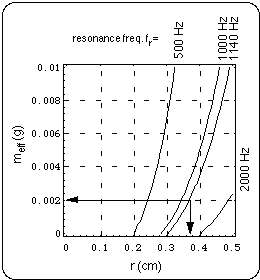
Fig. 4: Plot of contours of constant resonance
frequency fr as a funtion of the ear canal radius r and the
oscillating effective mass meff.
Example marked by arrows: for r = 0.37 cm and meff
= 0.002 g the resonance frequency is fr = 1140 Hz.
As the contour plot Fig. 4 shows, a possible choice for
fr = 1140 Hz is:

= 0.00129
g/cm3
V = 1.36 cm3
m = V
+ meff = (0.0018 + 0.002) g = 0.0038 g.
III.1.1 Example
Definitions and data
Definitions of frequencies characteristic of system
-
resonance frequency: Xa = 0,
-
equivalence frequency: |Xa|/Ra = 1.
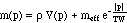
Choice of dependence of V and meff on air pressure
p established by tympanometer in ear canal:
(29) 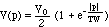
(30) 
Data used in Example:
(31) V0 = 1.36 cm3, TW = 40
daPa = 400 Pa (with 1daPa = 10 Pa)
(31a) meff = 0.002 g, Ra = 1000 ohm, r
= 0.37 cm, = 0.00129
g/cm3.
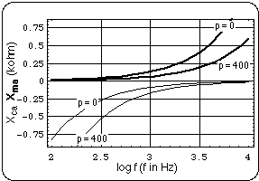
Fig. 5: Plot of the two components of the reactance
as functions of immission frequency f. Heavy curves represent mass
reactances, light curves compliant reactances.
Curve parameter is the ear canal pressure p.
Curves are plotted for p = 0 and p = 400 daPa. (for implementation of p
see (29) and (30)).
|
. |
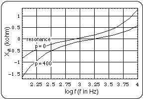
Fig. 6: Plot of total reactance
as a function of immission frequency f for fixed ear canal pressures p
= 0 and p = 400 daPa. At resonance Xa = 0. |
. |
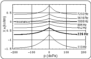
Fig. 7: Plot of total reactance as a function of
ear canal pressure p. Curve parameter is the immission frequency f. Curves
are plotted for f =113 Hz and the following 6 octaves above 113 Hz. |
. |
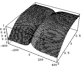
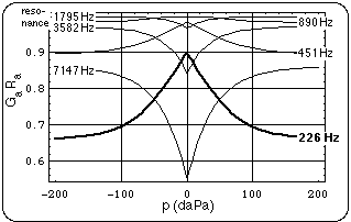
Fig. 8: GaRa as a function
of both ear canal pressure p (daPa) and immission frequency f (log f is
used, with f in Hz).
3D-plot: p is plotted along the x-axis (range: -400 daPa
<p < 400 daPa), log f is plotted along the y-axis (range: 2 <
log f < 3.7).
2D-plot: GaRa(p) is plotted with
f as parameter, i.e for f fixed at 226 Hz and the 5 following octaves above
226 Hz.
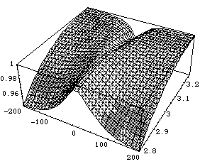
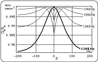
Fig. 9: Detail of Fig. 8 near resonance at zero
ear canal pressure, p = 0.
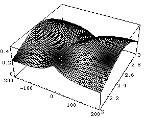
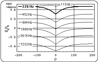
Fig. 10: BaRa as a
function of both ear canal pressure p (daPa) and immission frequency f
(log f is used, with f in Hz).
Left: 3D-plot, p is plotted along the x-axis (range:
-400 daPa < p < 400 daPa), log f is plotted along the y-axis (range:
2 < log f < 3.7).
Right: 2D-plot BaRa(p) with f as
parameter.
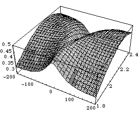
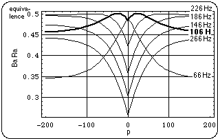
Fig. 11: Detail of Fig. 10 near equivalence
frequency at zero ear canal pressure p = 0.
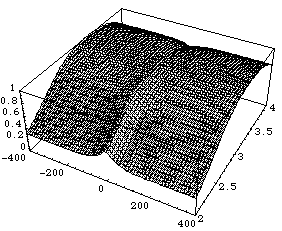
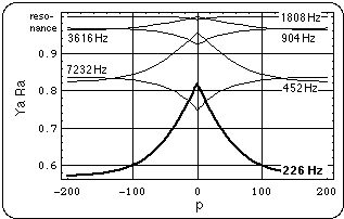
Fig. 12: YaRa as a
function of both ear canal pressure p (daPa) and immission frequency f
(log f is used, with f in Hz).
Left: 3D-plot, p is plotted along the x-axis (range:
-400 daPa < p < 400 daPa), log f is plotted along the y-axis (range:
2 < log f < 3.7).
Right: 2D-plot YaRa(p) with f as
parameter.
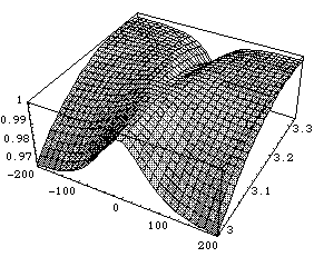
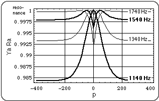
Fig. 13: Detail of Fig. 12 near resonance
at zero ear canal pressure p = 0.
Graphical Construction of GaRa(log
f), BaRa(logf)
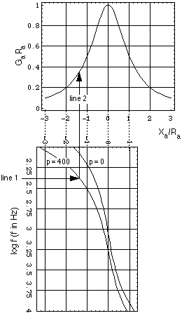
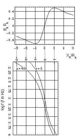
Fig. 14: Graphical explanation of shapes of curves
in Figs. 8 - 11:
Lower plots: Xa/Ra as functions
of f for fixed p = 0 and p = 400 daPa (see Fig. 6).
Upper plots: GaRa and BaRa
as functions of Xa/Ra (see Fig. 1).
To obtain a value GaRa for a given
immission frequency f
(1) choose f and read Xa/Ra from
lower plot (follow line 1 in direction of arrow),
(2) then read GaRa for Xa/Ra
(follow line 2 in direction of arrow).
III.2 Coupled Systems
(fit of acoustical behavior with an electrical network model
after Zwislocki)
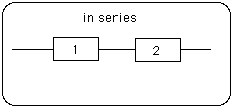
Fig. 15 Electrical system composed of 2 subsystems
(1) and (2) arranged in series.
|
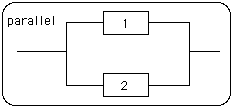
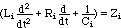
Fig. 15': Electrical system composed of 2 subsystems
(1) and (2) arranged in parallel. |
| Definition 10 (complex electrical resistance -"impedance", Z)
(32) 
|
. |
| Observation (Ohm's Law for complex resistance)
Let U be the voltage between entrance and exit terminals of a system
i and qi the electric charge in system i. Then the charge qi is proportional
to the applied voltage U:
(33) 
The same is true for a composite circuit:
(34) 
|
. |
Observation
The flow of charges through subsystems arranged in series is the same
in each subsystem:
(35) 
|
Observation
Charges in parallel subsystems add up in composite circuit:
(35')  |
| Theorem 6 (Composite resistances)
The composite resistance Z of a system composed of subsystems arranged
in series is:
(36) 
Proof:
Definition of Z:
(37) 
From (35) follows:  .
Comparison with (37), the definition of Z ( i.e. with U = q Z), follows
Z = Z1 + Z2. .
Comparison with (37), the definition of Z ( i.e. with U = q Z), follows
Z = Z1 + Z2.
|
Theorem 6' (Composite resistances)
The composite resistance Z of a system composed of subsystems arranged
in parallel is calculated as:
(36') 
Proof:
Plugging in observation (35') into Ohm's Law (34)
 . Division
of both sides with U yields . Division
of both sides with U yields
 . .
|
III.2.1 Example: 2-Component system
with subsystems arranged in parallel
(Fig. 15')
Data used in calculations
(Mathematica MR 1, 2 "2-Component System")
meff1 := 0.1 g; R1 := 1000 ohm;
meff2 := 0.01 g; R2 := 300 ohm;
r1 := 0.4 cm; r2 := 0.37 cm;
V1 := 0.9 cm3; V2 := 0.2 cm3;
1 :=
0.001 g/cm3; 2
:= 0.00129 g/cm3;
TW = 40 daPa.
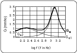
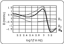
Fig. 16: Conductance Ga and susceptance
Ba plotted as functions of immission frequency f. Because of
(36')
Ga = Ga1+ Ga2, and Ba = Ba1
+ Ba2.
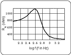
Fig. 17: Resistance R of the composite system as
a function of immission frequency f. By (36') 1/R
= 1/R1 + 1/R2.
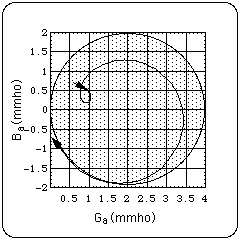
Fig. 18: Oscillation of composite system in {Ga,
Ba} plane. The point {Ga,(f) Ba(f)} runs
on the curve in the direction indicated by the arrows, when f runs from
100 Hz to 4111 Hz. The circle has been drawn to emphasize non-circular
form of curve.
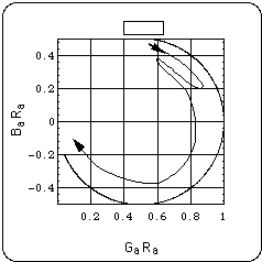
Fig. 19: Oscillation of composite system plotted
in {GaRa, BaRa} plane lies
on circle with radius 1/2. The reason for this is the linearity of the
composite system: The oscillation of each subsystem lies on this circle
(see Fig. 2), thus the linear composition of
these oscillations lies on that circle, too. The curve drawn by hand indicates
how the point {GaRa, BaRa} runs on the circle when f runs from 110 Hz (arrow
near {0.6, 0.4}) to 4060 Hz (arrow ending near {0.1, -0.1}).
III.3 Fit of measured tympanometric data
with linear model
In Fig. 17-17, R.H. Margolis and L.L. Hunter
present a multifrequency tympanogram. In that particular caase, the tympanic
membrane had the highest mobility at an ear canal pressure p = - 250 daPa.
Ga and Ba measured at this ear canal pressure are
plotted as functions of the immission frequency f in the following Figs.
20 and 21.
Fig. 22 results when these Ba are plotted vs. Ga.
The data are then analysed with a linear model. This means that the
deviation of the curve in Fig. 22 from a circle will be interpreted as
resulting from a frequency dependent resistance Ra(f) according
to (27). This may or may not be justified. It is simply
a method of condensing the measured data into a set of equations (the ones
developed in this paper) and corresponding parameters (necessary to evaluate
the equations).
After calculating Ra(f) with (27) (Fig.
23), BaRa is plotted vs. GaRa,
resulting in the circle presented in Fig. 24. The curve in Fig. 24 drawn
by hand indicates how the point {GaRa, BaRa}
runs first clockwise and finally counterclockwise on the circle when f
runs between 230 Hz (arrow at beginning of clockwise part) and 1930 Hz
(arrow at end of counterclockwise part). The circle crosses the abscissa
(GaRa-axis) at f = 1350 Hz (by definition
the resonance fr of the system).
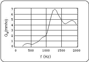
Fig. 20: Conductance Ga as a function
of the immission frequency f. The ear canal pressure is p = - 250 daPa.
Data from Margolis and Hunter.
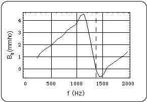
Fig. 21: Susceptance Ba as a function
of the immission frequency f. The ear canal pressure is - 250 daPa. Resonance
frequency fr is defined here as the frequency at which Ba
= 0 (fr = 1350 Hz, dashed line). Data from Margolis and Hunter.
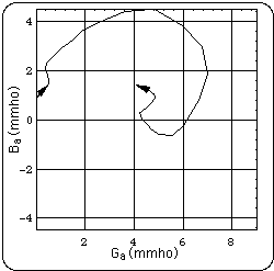
Fig. 22: Ba(f) plotted vs. Ga(f).
Ba(f) and Ga(f) as presented in Fig. 20, 21. The
curve starts at fi = 226 Hz and ends at fi
= 2000 Hz.
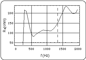
Fig. 23: Resistance extracted from oscillation
presented in Fig. 22 with method given by eq. (27).
Immission frequencies fi used by multifrequency tympanometer
are marked as dots in lower part of graph. They start at fi
= 226 Hz and end at fi = 2000 Hz. Dashed line marks resonance
frequency fr = 1350 Hz. Sampled frequncies fi miss
resonance fr.
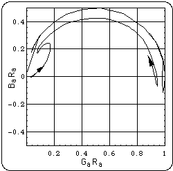
Fig. 24: Ba(f)Ra(f) plotted
vs. Ga(f)Ra(f). Data from Margolis and Hunter.
version: 29. July 2002
Location of this page
Home
Joachm Gruber